
0
Owner's of the Cisco Systems Car Stereo System Cisco Aironet 7-dBi Diversity patch Antenna gave it a score of 0 out of 5. Here's how the scores stacked up:
6
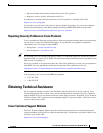
Cisco Aironet 7-dBi Diversity Patch Antenna (AIR-ANT5170P-R)
78-16468-02
Installing the Antenna
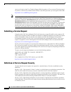
Mounting on a Vertical Surface
Follow these steps to mount your antenna on a vertical surface. This procedure describes mounting the
antenna on a drywall surface. If you are mounting the antenna on any other type of surface, your
procedure may vary slightly.
Step 1 Determine the location in which you will mount the antenna.
Step 2 Use the antenna as a template to mark the locations of the four mounting holes.
Step 3 Use a drill and a 3/16-in. (4.7 mm) drill bit to drill four holes at the locations you marked in Step 2.
Step 4 Start a plastic anchor into each hole.
Step 5 Use a mallet or small hammer to seat the anchors into the wall.
Step 6 Install a flanged washer on each #8 screw. Make sure the flange end of the washer faces out.
Step 7 Align the antenna’s mounting holes with the anchors.
Caution Make sure the antenna cables are pointing down (towards the ground) to ensure proper orientation. If the
antenna is not mounted properly, degraded performance could result.
Step 8 Holding the antenna in place, start the #8 screw into each antenna mounting hole.
Step 9 Use a Phillips screwdriver to secure the antenna to the wall. Do not overtighten.
Step 10 Install the end caps onto the flanged washers.
Caution If you install additional lengths of antenna cable, be sure to install a suitable strain relief. The antenna
may be damaged if you do not eliminate the extra weight of the cable. The antenna is not designed to
support the weight of a cable longer than the installed 3-ft (91.4 cm) cable.
Antenna Cable Information
Note Coaxial cable loses efficiency as the frequency increases, resulting in signal loss. The cable
should be kept as short as possible because cable length also causes signal loss (the longer
the run, the greater the loss).
Note The antenna cable has a 0.5 in. (12.7 mm) bend radius. Sharply bending or crimping the cable may cause
a degredation in performance.
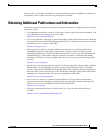
The antenna terminates with a RP-TNC plug after a short, 3-ft (0.91-m) cable. The mating connector to
the antenna is an appropriate RP-TNC jack. The connector on the opposite end will vary according to
the type of equipment used.


Find Your Products By Category
- Communications
- Photography
- Portable Media
- Home Audio
- Kitchen Appliance
- Computer Equipment
- TV and Video
- Cell Phone
- Household Appliance
- Video Game
- Laundry Appliance
- Musical Instruments & Equipment
- Power Tools
- Automotive
- Car Audio and Video
- Outdoor Cooking
- Marine Equipment
- Lawn and Garden
- Personal Care
- Fitness & Sports
- Baby
Please Login
