
0
Owner's of the APC Fan InRow gave it a score of 0 out of 5. Here's how the scores stacked up:
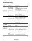


41InRow SC Operation
Local display is not
operational, but
cooling unit
operates
• Local display not connected
properly
• Verify that the local display cable is connected properly.
Incorrect air
pressure
• False filter clogs • Verify that the ends of the clear plastic air tubes are not
obstructed.
• Verify that the clear plastic air tubes are connected to the
controller.
• Verify that the clear plastic air tubes are not pinched.
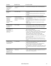
Alarms do not
display on
monitoring
equipment
(Customer Output
Contact)
• External monitoring
equipment is not receiving
power or is not functioning
properly
• Confirm that power, if required, is being supplied to the
external equipment.
• If the cooling unit is providing power (+12 V or +24 V) to
the external equipment, verify that the external equipment
is <
20 mA.
• Test the external equipment by bypassing the customer
output contact.
Cooling unit does
not shutdown on
command
• Drive voltage • Verify that there is a drive voltage entering the cooling unit.
You may use the available +12 V or +24 V power located
near the cooling unit. You must then also use the ground.
No communication
with building
management system
(BMS) port
• Improper connection • Confirm that the cooling unit is connected to the BMS port
and not to the Control port.
• Make sure that the wire polarity is correct.
Using a DC voltmeter, test the signal with no transmissions
in progress: Pin 2 should be greater than Pin 1 by at least
200 mV. Measure the cooling unit with the cable
disconnected, and then measure it again with the cable
connected. If the signal is less than 200 mV, the cooling unit
may be reverse-wired.
• Make sure that every cooling unit has either two sets of
wires in its connector OR one set of wires and a 150–ohm
resistor.
Cooling units are
not communicating
with each other
• A-Link failure • Verify that the actual number of cooling units in the group
matches the group number setting.
• Verify that the A-Link ports of every cooling unit have
either two cables or one cable and a terminator.
• Confirm that the A-Link cables are connected to the A-Link
ports and that a network cable is connected to the network
port.
Output air is 17°C
(62°F) and fans are
running at a very
high rate of speed.
• Upper or lower supply air
sensor fault
• Either the upper or lower supply air temperature sensor has
a fault. Verify that both supply air temperature sensors are
installed and working properly.
Problem Possible Cause Corrective Action


Find Your Products By Category
- Communications
- Photography
- Portable Media
- Home Audio
- Kitchen Appliance
- Computer Equipment
- TV and Video
- Cell Phone
- Household Appliance
- Video Game
- Laundry Appliance
- Musical Instruments & Equipment
- Power Tools
- Automotive
- Car Audio and Video
- Outdoor Cooking
- Marine Equipment
- Lawn and Garden
- Personal Care
- Fitness & Sports
- Baby
Please Login
