
0
Owner's of the Alesis Car Amplifier MULTIMIX gave it a score of 0 out of 5. Here's how the scores stacked up:


Operating Instructions
Multimix 12R Reference Manual 27
Metering/Unity Gain method
This method gives you more headroom than the peak method, while
maintaining a low noise floor which will be well below the noise of
most PA or live recording environments.
1. With the mic or line level signal flowing through the channel, set
the TRIM to minimum.
2. Set the CHANNEL FADER to 0 (about 2/3 up). Set all other
channel faders to minimum (off).
3. Set the MASTER fader to 0 dB (all the way up).
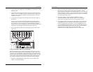
4. Observe the Multimix 12R's LED Meter. Adjust the [TRIM]knob
until the average signal level on the meter is about 0 dB (highest
green LED), or peaks do not exceed the +10 dB LED (or whatever
maximum your system is designed for). If you ever see the
channel's PEAK LED flash, you are within 6 dB of signal overload.
Turn down the TRIM knob until the PEAK LED stops flashing.
Operating Instructions
Typical Fader and Control Levels
Ideally, after you have set the [TRIM] controls, both the Channel and
Master faders should be run between the -10 dB and 0 dB position
(about 1/2 to 3/4 of the way up the fader travel on the channels, and
3/4 to full on the master) if possible. This position gives the greatest
amount of headroom and low noise. It also allows for any additional
increase or decrease in level that might be required during mixing.
Ultimately, the fader levels are dependent on the requirements of the
mix; these suggestions are only a starting point.
Unity gain points
Unlike many other mixers, the Multimix 12R's [MASTER] fader is
designed for unity gain (0) when the fader is up full, not at 3/4 or 1/2
of the travel. This allows you greater control to use the fader for
smooth, gradual fade-outs. It also discourages inexperienced
operators from using the mixer incorrectly.
The channel faders' unity gain point is at the traditional 3/4 point, with
10 dB of gain at the full-up position.
Trim gain ranges
The amount of gain in the TRIM circuit is shown on the front panel.
On channels 1-8, the LINE input ranges from 10 dB attenuation to 40
dB gain, a range that should cover almost any line signal. The MIC
input ranges from +10 dB to +60 dB gain, since the very low output
voltages of microphones need to be amplified a great deal. The stereo
channels' TRIM controls can be set from -15 dB attenuation to +15 dB
gain. See the Level Diagram near the end of this manual for a graphic
display of the gain structure of the mixer.
Aux Send levels
The nominal or unity gain points of the Aux 1 and Aux 2 controls are
at the “2 o’clock” position. At the full clockwise setting, they have 10
dB of gain. However, in most applications you won’t need that gain, if
the TRIM controls have been set properly. (See “How to Set Aux Send
and Return Levels” later in this chapter for more information.)


Find Your Products By Category
- Communications
- Photography
- Portable Media
- Home Audio
- Kitchen Appliance
- Computer Equipment
- TV and Video
- Cell Phone
- Household Appliance
- Video Game
- Laundry Appliance
- Musical Instruments & Equipment
- Power Tools
- Automotive
- Car Audio and Video
- Outdoor Cooking
- Marine Equipment
- Lawn and Garden
- Personal Care
- Fitness & Sports
- Baby
Please Login
